History of a remote control for aqueduct
Pubblicato da ing. Roberto Pozzi in SCADA · Mercoledì 05 Giu 2024 · 4:30
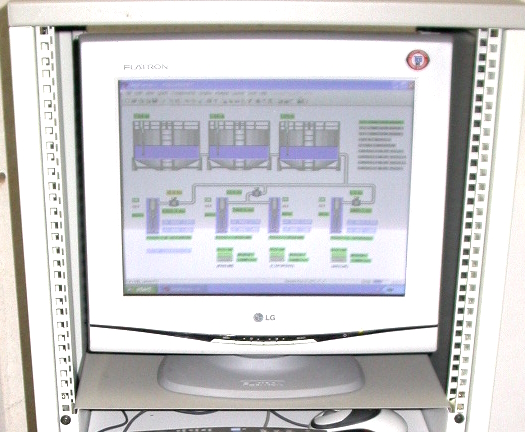
At the beginning of the 2000', a project was developed by Elcosys for the modernization and up-grade of a pre-existing automatic control system for the Municipal Aqueduct of Ghemme, a city in province of Novara, north-west Italy.
This project involved the implementation of an automatic remote control system for the activation and monitoring of remote pumping stations, based on the acquired data on the level of the reservoirs, pressure, and flow level in the main pipes.
The main project specifications were:
- Extreme reliability of operation, as it is a strategic control intended to guarantee 24-hour water supply for a municipality of about 4,000 people.
- Simplicity of management and maintenance of the system, which did not require the intervention of particularly specialized technicians
- Remote acquisition of data and characteristic parameters of the entire system with presentation on a monitor in the control room and remote accessibility by the administrators and technicians of the municipality.
- Expressed desire by the client was not to use the Internet in order to maximize security and to use, if possible, the existing wired network interconnecting the industrial modems of the various stations.
By carefully analyzing the project data and the characteristics of the existing technological systems and infrastructures, it became clear that the ideal system was to implement a SCADA System as a central control supervisor, communicating in real time with the remote RTUs that would locally manage the incoming and outgoing data traffic, for the acquisition of physical quantities from the various transducers and the activation of the pumping systems and safety solenoid valves. The SCADA system would have guaranteed high-level intelligence with analytical monitoring to manage the process automation logic, while the local controllers would have performed the logical and safety functions and local I/O traffic with the speed required by a real-time system. The RTUs operate as SCADA slaves with opcodes compiled in Assembler to maximize response speed and can generate triggered interrupts from local sensors, to forward requests to the SCADA control panel.
The hardware of the control room, based on Industrial PC, implementing a data acquisition and remote control system with SCADA program, connected in point-to-point mode via analog MODEMs on dedicated lines at 9600 bps (l max = 5600 m), suitable for the supervision and control of an aqueduct with multiple wells and remote water reserve tanks.
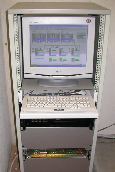
Main standard 19” rack cabinet of the supervision center composed of the following modules:
- 1 industrial PC in 19” 4U Rack Drawer - PENTIUM IV 3 GHz / 512MB RAM / HD 200 GB / 8-port Multiserial Card / 48X Burner / Sys. Op. Windows XP PRO
- 3 Analog MODEMS in 19” 2U drawer Conexant HV92-KX for dedicated line
- 1 ELCOSYS ELC-8870 relay control card
- 1 ELCOSYS LAB-U12 USB control unit - 16 12-bit analog inputs and 16 TTL digital I/O
- 1 Stabilized power supply 13.8VDC 2A for powering all modules
- 1 Industrial grade UPS in 19” 2U 220VAC 500W
Main standard 19” rack cabinet of the supervision center
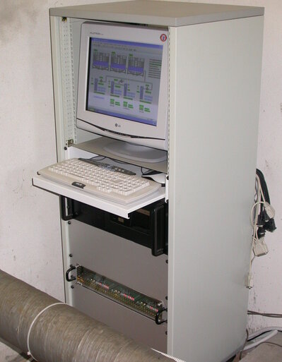
The SCADA PC in the Control Room, is connected via leased line MODEM to the remote RTU IDROLOG80-SL V.1.0 described as follows:
REMOTE ACQUISITION SYSTEM IDROLOG80-SL V.1-0
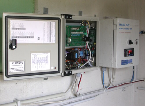
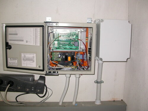
The IDROLOG80-SL microprocessor control units (slave) implement a data acquisition and remote control system, managed by an industrial supervision PC with SCADA program, connected in point-to-point mode via an analog modem on a dedicated line at 9600 bps, suitable for the supervision and control of an aqueduct with multiple wells and remote water reserve basins. Each control unit is composed of the following modules:
- 1 SPQ-Z80 microprocessor for analog data acquisition, relay control and data TX
- 1 SPQ-REL8 relay board for controlling local equipment and the modem
- 1 SPQ-UIO I/O board for connecting sensors and/or transducers to the inputs
- 1 Conexant HV92-KX analog modem for connection to the remote central PC
- 1 13.8VDC 1A stabilized power supply for powering all modules
- 1 Backup battery powered in buffer for the above cards
- 1 0-20 mA constant current generator for testing
The main meters used in the plant at the 4 pumping stations are the KROHNE IFC 010 D digital flow meters which send the data to the IDROLOG80 RTUs which in turn transmit the collected data to the SCADA central.
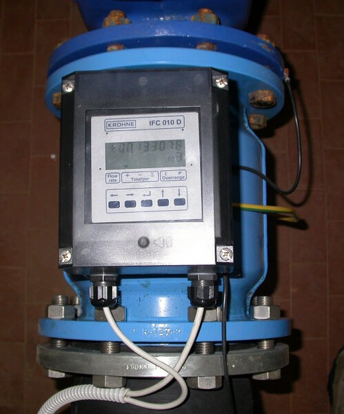
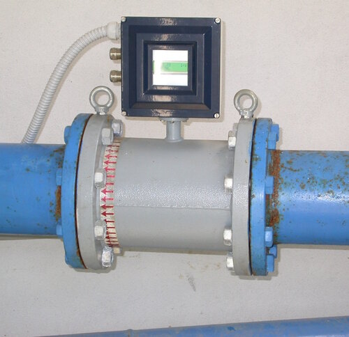
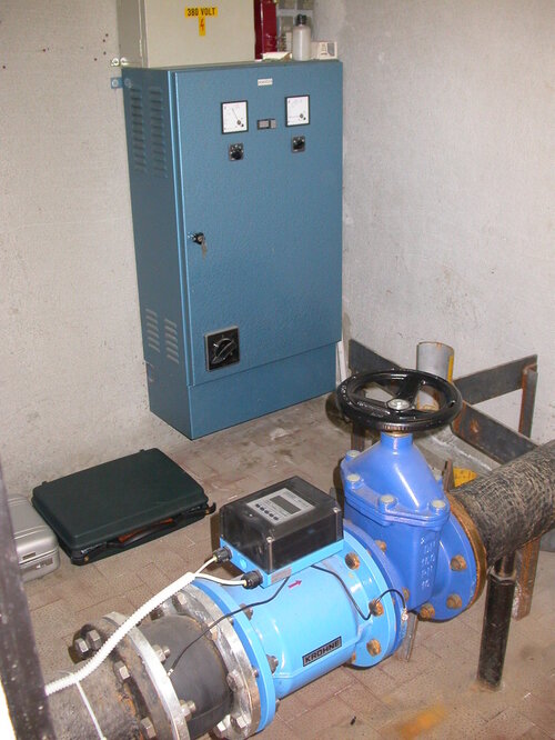
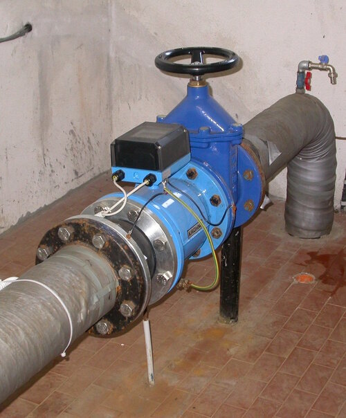
The IDROLOG80 control system is implemented by a main program that operates in the SCADA DAQFACTORY environment and acquires the physical parameters of the water network, i.e. flow, pressure and tank level, in order to provide real-time regulation of the flow rate of the pumping stations with the aim of maintaining a constant water level in the 3 elevated tanks, according to the set point and hysteresis parameters set. The remote control units (RTU) send the measured physical quantities to the SCADA control unit and from it receive the actuation signals of the electric pumps and solenoid valves. The SCADA system also allows you to collect and archive the history of partial and total water consumption data, providing the related graphs and statistics.
